 01
PPS-ICP / PPS-CHG
IEPE & Charge-Mode Piezoelectric Pressure Transducers
AC pressure pulses. IEPE voltage output or external charge conditioning.
Review this route ↗DYNAMIC PRESSURE / ENGINEERED IN THE DETAILS
The peak is only part of the story. Specify the leading edge, the static baseline and every link between your pressure port and the recorded signal.
A narrow-band process chain can attenuate a fast event. Response depends on the sensor, port, cable, conditioning and acquisition—not the output format alone.
Understand the chain ↗01 / SELECT BY THE SIGNAL
Start with what must be preserved. Then define the configuration.
01PPS-ICP / PPS-CHG
AC pressure pulses. IEPE voltage output or external charge conditioning.
Review this route ↗ 02
PPS-BLT / PPS-UWS
Incident free-field, reflected-wall and liquid-coupled measurement geometries.
Review this route ↗ 03
PPS-PRZ
Retain the steady baseline alongside changing pressure.
Review this route ↗ENGINEER THE COMPLETE PRESSURE CHAIN
Ready to compare specific arrangements? Filter eight source-documented configurations and download a model brief.
Find a model & range ↗Specify a water-hammer measurement around the static line pressure, pulse amplitude and installed timing response. Select a piezoelectric dynamic chain or a DC-coupled bridge when the steady baseline must remain visible.
Define a chamber-pressure measurement by its range, pulse shape, sealing geometry and conditioning. A requested envelope to 700 MPa is reviewed per configuration; it is not a rating of every sensor in this family.
Complete the dynamic-pressure chain with the correct input type, gain, excitation and response. IEPE current supplies, charge amplifiers and differential bridge conditioners perform different jobs.
Resolve combustion pulsation with a charge-output chain selected for the actual thermal duty. Specify the gas, diaphragm, body and cable temperatures separately before choosing a sensor or cooling arrangement.
Specify a cylinder-pressure channel around the engine port, cyclic waveform and thermal exposure. A miniature thread or charge output does not by itself establish hydrogen compatibility or a correct front seal.
Define whether the channel must identify shock arrival, recover a calibrated pressure waveform, or do both. A timing pulse can be useful without providing an accurate pressure amplitude.
Select the sensing material, active aperture and calibrated acoustic chain together. A PVDF needle hydrophone, a tourmaline shock probe and a piezoresistive underwater sensor are separate measurement routes.
Measure mean surface pressure and its fluctuations with a DC-capable bridge package reviewed against the actual surface. Thickness, bonding, cable routing and acoustic aperture all affect the installed measurement.
Retain a static pressure baseline in a hot-medium installation with a specifically reviewed cooled bridge assembly. The gas temperature and the sensing element’s temperature are different limits.
02 / DEFINE THE REQUIREMENT
A resonant frequency is not a flat measurement bandwidth. A range rating is not a shock qualification. Put timing, amplitude and installation into the same engineering brief.
Read the selection guide ↗03 / APPLICATION BRIEFS
A propulsion test can require a mean-pressure channel, a fast fluctuation channel and a common timing reference. Plan each measurand and exposure separately before combining their records.
Plan the pressure channels ↗Select pressure channels for the record your battery test needs: enclosure pressure buildup, a vent-related transient or a separate chamber-pressure event. Each location has a different pressure and thermal boundary.
Plan the pressure channels ↗Instrument a cooling-loop transient around normal line pressure, the event location and the required waveform. Review coolant compatibility and the pressure port alongside sensor speed.
Plan the pressure channels ↗Retain mean surface pressure and unsteady fluctuations with miniature bridge channels selected for the model geometry. Installed aperture, surface disturbance and phase response matter alongside the sensing element.
Plan the pressure channels ↗Choose a cylinder-pressure channel, a thermoacoustic fluctuation channel or a DC-capable hot-medium channel against its own requirements. Shared fuel terminology does not make those installations interchangeable.
Plan the pressure channels ↗SOURCE-DOCUMENTED HARDWARE REFERENCES
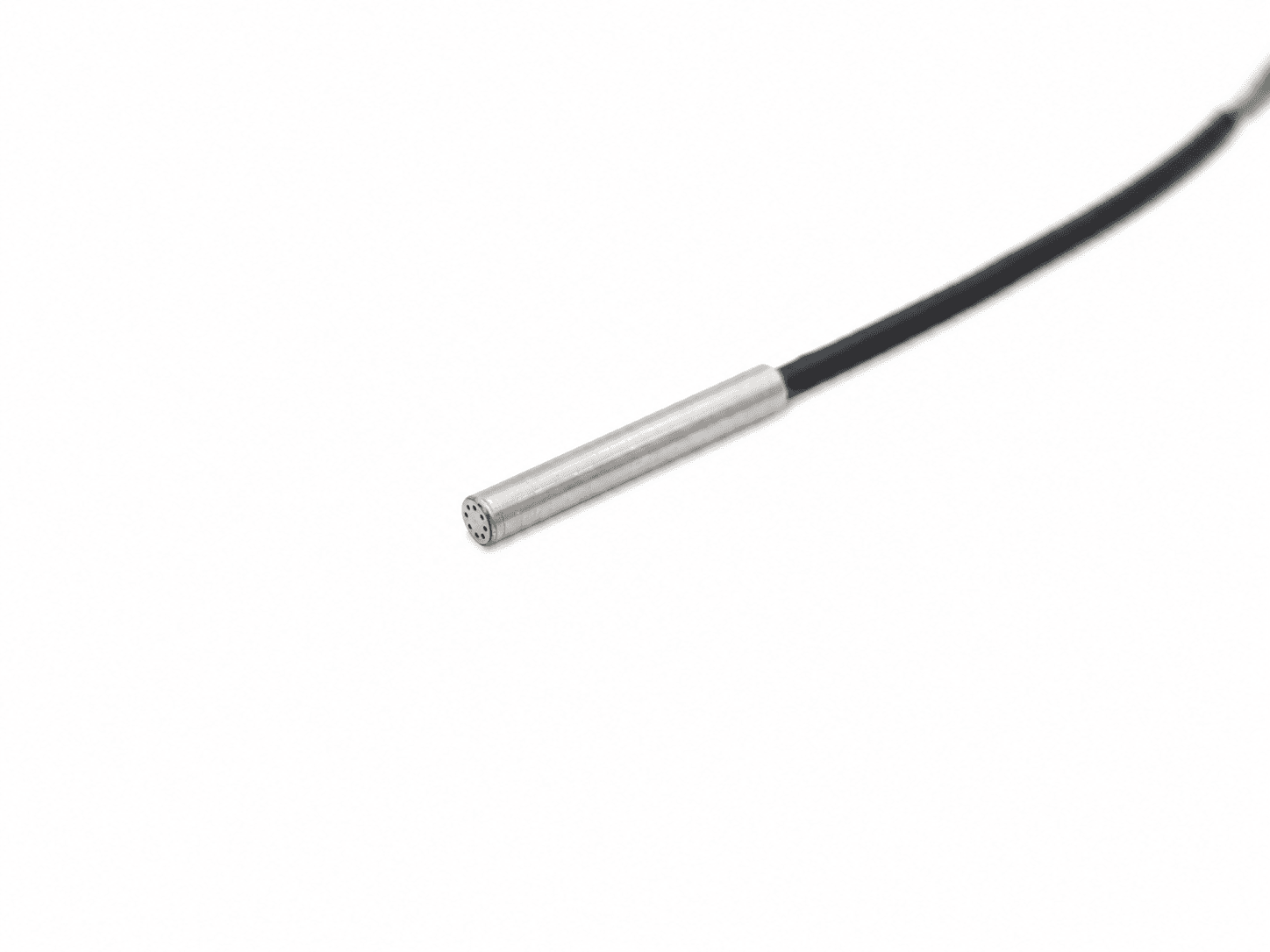
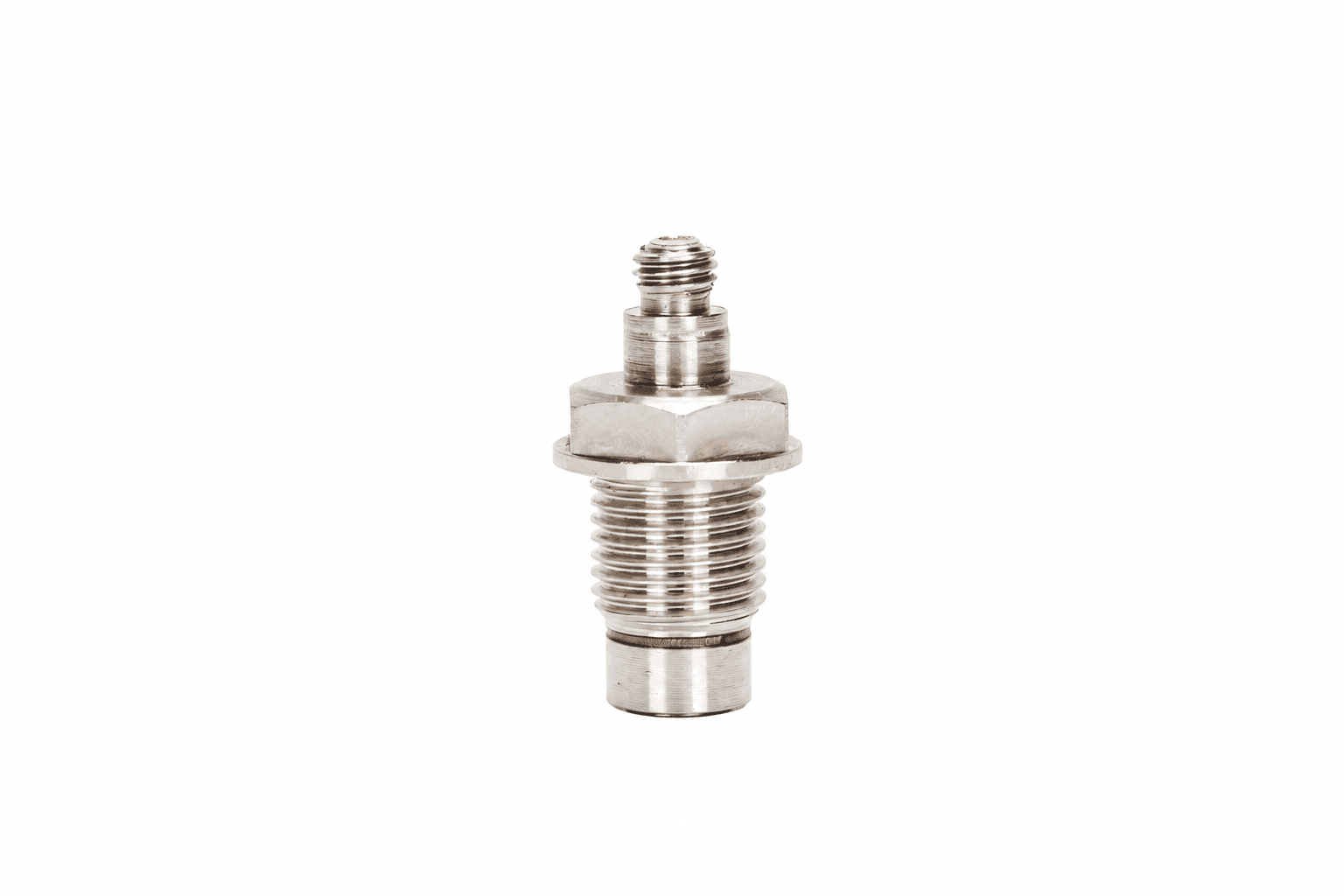
These supplier-reference images show the indicated arrangements. Final pressure, medium, dimensional and response requirements are confirmed for the proposed configuration.
COMPLETE THE PRESSURE MEASUREMENT CHAIN
Optional budget requests. Confirm the input type, response, channel count and installed compatibility. Specialist hydrophone preamplifiers, hot-zone hardline cables and cooled assemblies are quoted separately.
PREPARE A REVIEWABLE BRIEF
These are blank engineering request/checklist documents. They are not released product datasheets, calibration certificates or signed quotations.
Record peak, baseline, timing, medium and acquisition requirements.
PDF / WORKSHEETReplacement-review worksheet ↗Compare the original and proposed configuration without prefilled compatibility claims.
PDF / WORKSHEETCalibration-deliverables checklist ↗Define the required sensitivity, response, uncertainty and traceability evidence.
PDF / WORKSHEETQuotation-scope worksheet ↗List requested quantities, options and documents for a written quotation.
START WITH YOUR TEST
Send the peak, baseline, required response and existing model. We will review the configuration and quotation requirements.
Send an engineering RFQ ↗